1. Abstract
This report is on Laurent Representation (a.k.a. PAM representation) of GMSK. According to Laurent, a CPM signal can be written as sum of several PAM signals. Laurent's representation of CPM signals resembles Fourier decomposition in many ways. This approach enables many different receiver types, most notably the serial receiver, which is found by Kaleh.You can find sample MATLAB codes here.
2. Introduction
GMSK waveform is a CPM scheme and can be modeled as sum of several PAM waveforms [1]. Luarent's representation enabled two new receivers for CPM signals, especially for GMSK [2, 3]. First one is a Viterbi Algorithm type of receiver and the second one is a serial receiver. Since there are other, easier to understand and implement Viterbi Algorithm receivers for GMSK, this one is not further investigated in this report. However, the computation cost of the serial receiver is very low, which is why this report is written.In the following section, mathematical background of PAM representation of CPM is further investigated. After that a sample problem is solved for a specific case for further clarification of the subject. Next, some remarks are reiterated for clarification of PAM representation. Finally, the serial receiver is implemented and simulation results are presented.
3. PAM Representation of CPM
A CPM signal has the following form [4]:s(t, \underline{\alpha}) = \sqrt{\frac{E}{T}}exp\{j\psi(t, \underline{\alpha})\},
where
\psi(t, \underline{\alpha}) = \pi h\sum_{i=0}^{n} \alpha_i q(t-iT), \quad nT \leq t < (n+1)T.
Here,
q(t) =
\begin{cases}
0, & t < 0, \\ \int_{0}^{t}f(\tau)d\tau, & 0 \leq t < LT,\\ 1, & t \geq LT \end{cases}
where
f(t) = \frac{1}{2T}\bigg[Q(2\pi B \frac{t-\frac{T}{2}}{\sqrt{ln(2)}}) - Q(2\pi B \frac{t+\frac{T}{2}}{\sqrt{ln(2)}})\bigg],
where
Laurent rewrote Eq.
s(t, \underline{\alpha}) = \sqrt{E}\sum_{k=0}^{2^{L-1}} \sum_{i=0}^{n-1} a_{k,n} h_k(t-nT),
where
In order to formulate
J \triangleq e^{jh\pi},
and
c(t) \triangleq \begin{cases}
\frac{sin(\pi h - \pi h q(t))}{sin(\pi h)}, & 0 \leq t < LT, \\ c(-t), & -LT < t \leq 0, \\ 0, & o.w. \end{cases}
with
exp\{j\psi(t, \underline{\alpha})\} = exp\bigg\{j\pi h\sum_{i=0}^{n-L} \alpha_i \bigg\} \prod_{i=n-L+1}^{n} exp\big\{j\pi h\alpha_i q(t-nT)\big\}.
This is very much like the Trellis like representation in [5]. Since for MSK,
c(t) \triangleq \begin{cases}
cos\Big(\frac{\pi q(t)}{2}\Big), & 0 \leq t < LT, \\ c(-t), & -LT < t \leq 0, \\ 0, & o.w. \end{cases}
In addition to this, in MSK
The product term in Eq.
exp\big\{j\pi h\alpha_i q(t-nT)\big\} = cos\big(\pi h\alpha_i q(t-nT)\big) +jsin\big(\pi h\alpha_i q(t-nT)\big),
which is equal to,
exp\big\{j\pi h\alpha_i q(t-nT)\big\} = \frac{sin\big(\pi h - \pi h q(t-nT)\big)}{sin(\pi h)} +J^{\alpha_i}\frac{sin\big(\pi h q(t-nT)\big)}{sin(\pi h)}.
Due to the properties of the Gaussian function
1-q(t) = q(LT) - q(t) = q(LT-t),
also using Eq.
\frac{sin\big(\pi h q(t)\big)}{sin(\pi h)} = c(t-LT).
All these definitions enable us to rewrite Eq.
s(t, \underline{\alpha}) = \sqrt{\frac{E}{T}} a_{0,n-L} \prod_{i=n-L+1}^{n} \bigg[J^{\alpha_i}c(t-nT-LT) + c(t-nT)\bigg].
Here
a_{0,n} = exp\bigg\{j\pi h\sum_{i=0}^{n} \alpha_i \bigg\} = a_{0, n-1}J^{\alpha_n} = a_{0, n-2}J^{\alpha_n}J^{\alpha_{n-1}}.
In Eq.
4. Example Solution for L=3
In order to fully visualize how PAM representation works, in this chapter a sample problem for s(t, \underline{\alpha}) = \sqrt{\frac{E}{T}} a_{0,n-3} \prod_{i=0}^{2} \bigg[J^{\alpha_i}c(t-iT-3T) + c(t-iT)\bigg].
Here, the product term is over
\begin{aligned}
s(t, \underline{\alpha}) = \sqrt{\frac{E}{T}} a_{0,n-3} \Bigg[ & \bigg(J^{\alpha_{n}}c(t-nT-3T) + c(t-nT)\bigg) \\ & +\bigg(J^{\alpha_{n-1}}c(t-nT-2T) + c(t-nT+T)\bigg) \\ & +\bigg(J^{\alpha_{n-2}}c(t-nT-T) + c(t-nT+2T)\bigg)\Bigg]
\end{aligned}
then multiplying all these terms result in:
\small
\begin{aligned}
s(t, \underline{\alpha}) = & \sqrt{\frac{E}{T}} a_{0,n-3} \\ &
\Bigg[ \bigg(J^{\alpha_{n}}J^{\alpha_{n-1}}J^{\alpha_{n-2}}c(t-nT-3T)c(t-nT-2T)c(t-nT-T)\bigg) \\ & +\bigg(J^{\alpha_{n}}J^{\alpha_{n-1}}c(t-nT-3T)c(t-nT-2T)c(t-nT+2T)\bigg) \\
& +\bigg(J^{\alpha_{n}}J^{\alpha_{n-2}}c(t-nT-3T)c(t-nT+T)c(t-nT-T)\bigg) \\
& +\bigg(J^{\alpha_{n}}c(t-nT-3T)c(t-nT+T)c(t-nT+2T)\bigg) \\
& +\bigg(J^{\alpha_{n-1}}J^{\alpha_{n-2}}c(t-nT-2T)c(t-nT)c(t-nT-T)\bigg)\\
& +\bigg(J^{\alpha_{n-1}}c(t-nT-2T)c(t-nT)c(t-nT+2T)\bigg)\\
& +\bigg(J^{\alpha_{n-2}}c(t-nT)c(t-nT+T)c(t-nT-T)\bigg)\\
& +\bigg(c(t-nT)c(t-nT+T)c(t-nT+2T)\bigg)\Bigg]
\end{aligned}
Next,
\begin{aligned}
& a_{0,n}c(t-nT-3T)c(t-nt-2T)c(t-nT-T) \\
& a_{0,n-1}c(t-nT-2T)c(t-nt-T)c(t-nT) \\
& a_{0,n-2}c(t-nT-3T)c(t-nt-2T)c(t-nT-T) \\
& a_{0,n-3}c(t-nT)c(t-nt+T)c(t-nT+2T) \\
\end{aligned}
\begin{aligned}
& a_{1,n}c(t-nT-3T)c(t-nt-T)c(t-nT+T) \\
& a_{1,n-1}c(t-nT-2T)c(t-nt)c(t-nT+2T) \\
\end{aligned}
\begin{aligned}
& a_{2,n}c(t-nT-3T)c(t-nt-2T)c(t-nT+2T) \\
\end{aligned}
\begin{aligned}
& a_{3,n}c(t-nT-3T)c(t-nt+T)c(t-nT+2T) \\
\end{aligned}
After
\begin{aligned}
s(t, \underline{\alpha}) = & \sqrt{\frac{E}{T}}
\Bigg[a_{0,n} h_0(t-nT) + a_{0,n-1}h_0(t-nT+T) \\
& + a_{0,n-2}h_0(t-nT+2T) + a_{0,n-3}h_0(t-nT+3T) \\
& + a_{1,n}h_1(t-nT) + a_{1,n-1}h_1(t-nT+T) \\
& + a_{2,n}h_1(t-nT) + a_{3,n-1}h_1(t-nT) \Bigg]
\end{aligned}
with
\begin{aligned}
& h_0(t) = c(t-3T)c(t-2T)c(t-T) \\
& h_1(t) = c(t-3T)c(t-T)c(t+T) \\
& h_2(t) = c(t-3T)c(t-2T)c(t+2T) \\
& h_3(t) = c(t-3T)c(t+T)c(t+2T) \\
\end{aligned}
and

5. Some Important Remarks on PAM Representation of CPM
In the previous chapter the CPM signal is written as summation of several PAM signals forHowever, the auxiliary symbols that belong to a particular
Thus, if PAM representation is considered at the receiver without doing anything at the transmitter, then the inherent differential encoding structure has to be differentially decoded at the receiver in order to go back to the original symbols. This also automatically means the receiver is non-coherent.
If a differential decoder is employed at the transmitter chain, then together with the inherent differential decoding of PAM representation at the receiver will yield net result of no encoding-decoding. This is because the symbols are pre-decoded at the transmitter and encoding them back due to PAM representation results in original symbols, which automatically resulting with the coherent receiver.
6. Serial Receiver
Serial receiver is developed according to the inherent differential encoding. As mentioned earlier, there are two receiver types, (a) coherent, (b) noncoherent. For all cases though, the received signal has the following form:z(t) = s(t, \underline{\alpha}) + n(t),
where
Now, lets assume that there is a hypothetical sequence of auxiliary symbols
\begin{aligned}
\Lambda & = Re\Bigg\{\int_{-\infty}^{\infty} z(t)\sum_{i=0}\hat{a}^*_{0,i}h_0(t-iT)dt \Bigg\} = Re\bigg\{\sum_{i=0}\hat{a}^*_{0,i} r_{0,i}\bigg\} \\
& = \sum_{i=0}a_{0,2i}Re \big\{r_{0, 2i} \big\} + Im \bigg\{\sum_{i=0}a_{0,2i+1}\bigg\} Im \big\{r_{0, 2i+1} \big\}
\end{aligned}
with,
r_{0,i} = \int_{-\infty}^{\infty} z(t)h_0(t-iT)dt.
This is basically the maximum likelihood sequence detection (MLSD) receiver and is the optimum one. Eq.
This idea is logical since if the GMSK is received using PAM representation, original bipolar NRZ symbols are encoded into complex auxiliary symbols. Complex auxiliary symbols follow a simple differential encoding scheme which encodes the original symbols into other
Next, for the serial receiver, we can make some further assumptions. Lets continue with the previous
First, the following equation is written again:
z(t) = \sqrt{E}\sum_{i=0}^{n-1}\bigg[a_{0,i}h_0(t-iT) + a_{1, i}h_1(t-iT)\bigg] + n(t).
This approximated signal is then passed through
\small
\begin{aligned}
z(t) & \ast h_0(-t) =\Bigg[\sqrt{E}\sum_{i=0}^{n-1}\bigg[a_{0,i}h_0(t-iT) + a_{1, i}h_1(t-iT)\bigg] + n(t)\Bigg] \ast h_0(-t) \\
& = \sqrt{E}\sum_{i=0}^{n-1}\bigg[a_{0,i}h_0(t-iT)\ast h_0(-t) + a_{1, i}h_1(t-iT)\ast h_0(-t)\bigg] + n(t)\ast h_0(-t)
\end{aligned}
Here, the following definitions are made in order to simplify the above equation,
\begin{aligned}
& r_{00}(t) = h_0(t-iT)\ast h_0(-t), \\
& r_{10}(t) = h_1(t-iT)\ast h_0(-t), \\
& n_{0}(t) = n(t)\ast h_0(-t), \\
\end{aligned}
Since the primary PAM component has the most energy in it, expectation is that auxiliary symbol
The CSI can be considered as a colored noise since in [2], it is shown that different auxiliary symbols that correspond to different PAM components are mutually uncorrelated. Thus serial reception with
Because of this, in [2], Kaleh employed a Wiener filter in order to minimize the effect of this additional term. However, Wiener filtering requires a good idea on the noise variance (hence SNR) in order to work properly. Thus, a different take on the Wiener filter applied in this report.
Lets assume that there is a filter
\begin{aligned}
& h_0(t-iT) \ast h_{opt}(-t) = \delta[iT], \\
& h_1(t-iT) \ast h_{opt}(-t) = 0, \\
\end{aligned}
so that correlation of the filter with
h_0(t) + h_1(t) = \sum_k c[k] h_{opt}(t-kT).
Right hand side of this equation is essentially a convolution as well.
Next, both sides of the equation are matched filtered with
h_0(-t)\ast \bigg[h_0(t) + h_1(t)\bigg] = h_0(-t)\ast \bigg[\sum_k c[k] h_{opt}(t-kT)\bigg],
and using the identities in Eq.
r_{00}(t) + r_{10}(t) = \sum_k c[k].
Putting this equality inside Eq.
h_0(t) + h_1(t) = \bigg[r_{00}(t) + r_{10}(t)\bigg]\ast h_{opt}(t-kT).
Taking the Fourier transform and then solving in the frequency domain and finally taking the inverse Fourier transform is an easier to solve for this filter. One important note is that
h_{opt}(t) can be computed and directly applied instead ofh_0(t) in sample domain, this filter would have more coefficients in total compared toh_0(t) ,c[k] can be computed and applied afterh_0(t) and a sampling block,h_00(t) andc[k] would both have much less coefficients in total compared toh_{opt}(t)
The following 4 receivers are the possible coherent and non-coherent receivers with different applications of the optimum filter.
7. Serial Coherent Receiver
Since PAM reception inherently employs differential encoding, in order to coherently receive with PAM representation, a differential decoder has to be employed at the beginning of transmitter [6, 2]. This differential decoder breaks the inherent differential encoding of the PAM representation, thus the received symbols in PAM representation become directly the original symbols. The block diagram of the coherent transmitter-receiver is in Fig. 2.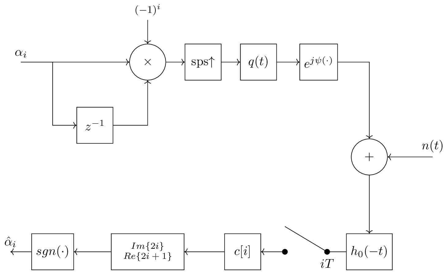
8. Serial Noncoherent Receiver
Previously, it is mentioned that the auxiliary symbols that belong to different PAM component are mutually uncorrelated. However, the same is not the case for the symbols that belong to the same PAM component. The relationship between the original symbols and auxiliary symbols are given in Eq.In [3], a method is given to weaken the correlation between the consecutive auxiliary symbols, which should increase the overall BER performance. The idea is basically to increase the depth of differential encoding additionally by employing a complex differential encoder.
A new parameter
\beta_i = (-1)^{\frac{M-1}{2}}\alpha_i \prod_{n=1}^{M-1}\beta_{n-1},
Thus
In [3], receiver for only odd numbers of
Since there is differential encoding in the system, this has to be differentially decoded in order to reach the original symbols at the receiver. The total depth of the differential decoder is
The block diagram of the transmitter and receiver is in Fig. 3. Here, differential decoder works on the complex signal where as the encoder's input is bipolar NRZ symbols. The gain block only applies

9. Conclusion
The corresponding BER curves for various other GMSK receivers and some BPSK receivers is shown in Fig. 4. In the figure,

10. References
[1] Pierre Laurent. Exact and approximate construction of digital phase modulations by superposition of amplitude modulated pulses (amp). IEEE transactions on communications, 34(2):150–160, 1986.[2] Ghassan Kawas Kaleh. Simple coherent receivers for partial response continuous phase modulation. IEEE Journal on Selected Areas in Communications, 7(9):1427–1436, 1989.
[3] Ghassan Kawas Kaleh. Differentially coherent detection of binary partial response continuous phase modulation with index 0.5. IEEE transactions on communications, 39(9):1335–1340, 1991.
[4] John B Anderson, Tor Aulin, and Carl-Erik Sundberg. Digital phase modulation. Springer Science & Business Media, 2013.
[5] Musa Tunç Arslan. Maximum likelihood sequence detector for gmsk. Technical report, Meteksan Defence Inc., 2018.
[6] Gee L Lui. Threshold detection performance of gmsk signal with bt= 0.5. In Military Communications Conference, 1998. MILCOM 98. Proceedings., IEEE, volume 2, pages 515–519. IEEE, 1998.


Hi, have you used CPM representation for an implementation of a gmsk transmitter ( modulator)
ReplyDeleteHello, after Eq. (25) it says "where s(t, α) is as in Eq. (5) ...", and Eq. (5) is the PAM representation. Sorry it's been years since I worked on these so I do not remember what I used exactly.
DeleteI also want to add, I posted several MATLAB codes, you can find the link at the top of the blogpost and check there. It includes both the transmitter and receiver.
Delete